
Best Practices for Optimizing Design for Manufacturing
Achieving excellent outcomes in plastic injection molding hinges on understanding the characteristics of thermoforming plastic resins and their behavior within a mold tool. Employing sound design practices early in the product development cycle is key to sidestepping typical challenges and enhancing the effectiveness of both mold tools and the resulting products. We aim to impart our insights into the prevalent causes of defects in mold tool design and provide guidance on avoiding them.
Bosses
A boss refers to a post or pillar designed to secure a screw for joining various components. Similar to other features, a boss can introduce thermal stress to a part, leading to sink marks. It is crucial to adhere to design best practices to optimize performance.
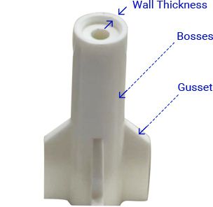
Bosses represent additional thermal mass in the part. They must be designed carefully to avoid creating sink marks.
Base Radius
Maintain a radius at the base, ranging between 25-50% of the wall thickness.
Connection to External Wall
Attach the boss to an adjacent external wall using a rib for added support.
Gussets for Reinforcement
Strengthen the boss with gussets, especially in high-stress applications.
Height Limitation
Ensure the boss does not exceed a height of 3 times the outside diameter.
Draft Angle
Implement a minimum draft angle of 1/2° on the outside. If a lesser draft is necessary on the inside, meticulous polishing of the tool and core is essential.
Spacing Between Bosses
Avoid placing two or more bosses closer than twice the adjacent wall thickness to prevent potential issues.
Draft Angle
The draft angle serves as a space between the face of a part feature and the respective wall of the core/cavity. It is crucial to align this angle parallel to the direction of the tool opening. Our tooling engineers may suggest varying angles based on factors such as resin type, surface texture, part geometry, and other considerations. The inclusion of a draft angle is essential to prevent the part from scraping or getting stuck against the tool wall during the opening process, ensuring a smooth and clean ejection.
Draft angles usually run parallel to the direction of the mold opening.
Ejector Pin Position
Not every design necessitates the use of an ejector pin. Alternatively, a stripper plate may be employed in certain instances to automatically release the part as the mold opens and closes. However, for parts requiring ejector pins—especially for intricate shapes—it's crucial to carefully consider the size, shape, and placement of these features.
Ejector pins play a pivotal role in pushing the finished part off the core of the mold. As the plastic remains somewhat pliable, these pins may leave a characteristic mark. Therefore, it is a best practice to clearly designate specific locations on your part design where pin marks won't adversely affect the part's appearance or performance. In certain scenarios, additional supporting areas may be required to provide a surface against which the ejector pin can operate effectively.
Gate Witness Marks
A gate serves as the entry point through which liquid resin is injected into the mold cavity. Various gate types are available to accommodate diverse functions and part geometries, and each type significantly impacts the corresponding part. Therefore, close collaboration with our clients is essential as we propose different gating options, ensuring complete filling of the part before the gate solidifies.
Regardless of the gate type chosen, it leaves a corresponding mark on the part. It is imperative for product developers to consider this factor and designate an area on the piece where the mark does not adversely affect its appearance or performance. This thoughtful consideration helps in strategically managing the gate witness marks for optimal outcomes in the final product.
The gate witness is a small dimple of plastic left behind on the part after molding.
Parting Lines
Parting lines are visible markings left on a part where the two mold halves come together and seal. While they can be challenging to entirely avoid, the optimal approach is for the designer to explore creative methods to seamlessly blend or conceal this line within the overall design. Our collaborative effort involves providing alternative suggestions to modify the tool, aiming to make the parting line less visible or concealed by another feature of the part. Additionally, the use of various surface textures can be considered to diminish the prominence of this line, contributing to a more aesthetically pleasing final product.
Ribs
Ribs serve as structural supports to reinforce wall sections without significantly increasing mass. While they play a crucial role in stiffening, it's essential to apply good design practices considering their impact on the distribution of thermal stress. Here are some guidelines:
1. Where a rib meets a wall, ensure the rib thickness is no greater than 50% of the wall thickness.
2. The base of the rib, where it intersects with the wall, should feature a radius between 25-50% of the wall thickness.
3. Restrict rib height to no more than three times the wall thickness.
4. Incorporate increased draft angles on ribs to facilitate easy release.
Gussets, akin to ribs but smaller, are employed to fortify the base of a feature. The same design principles that apply to ribs are relevant for gussets. These guidelines help maintain structural integrity and ensure optimal performance in the final product.
Ribs add strength while avoiding excess mass which can cause sink marks.
Sink Marks
Sink marks occur when the hot liquid resin within the mold undergoes cooling and subsequent contraction. This contraction leads to the formation of divots on the surface of the parts, with more pronounced marks in regions that have relatively more mass. Thus, achieving a careful balance in the distribution of material is crucial for product designers. To assist in optimizing designs, a detailed MoldFlow analysis is provided, highlighting areas where sink marks are more likely to occur.
While valuable tips have been shared above, recognizing the complexity of this subject, we have also crafted a helpful white paper for further insights.
We use MoldFlow software to analyze potential shrink marks as well as other preventable defects.


